TTL TV-Tennis
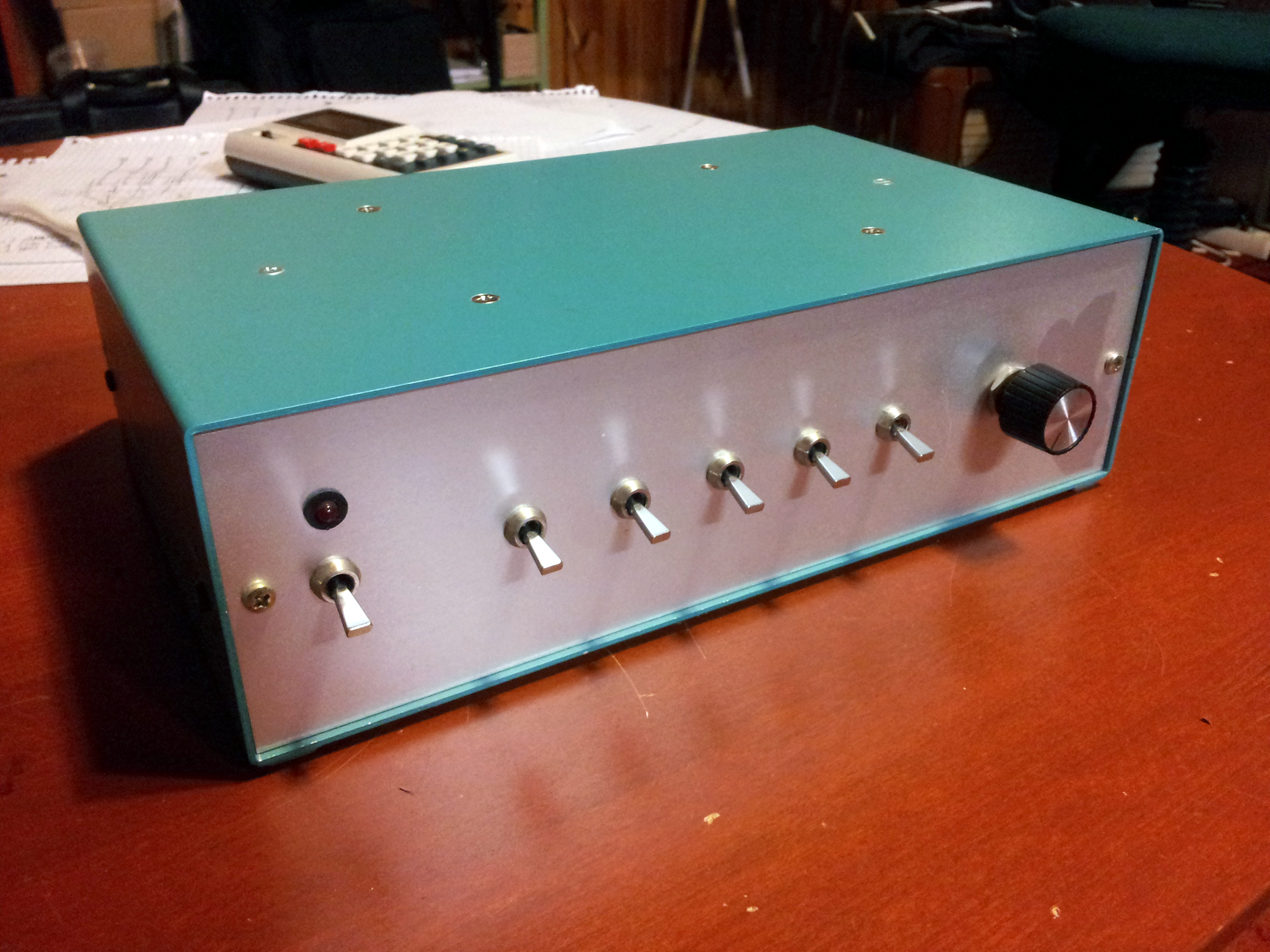
Early birdie of first working prototype:


Progress... (August 2012)
...After 3½ years, in the corner of a dusty shelf...
I have now finished the basic version of TV Tennis mentioned in Elektor issue 7 and it works great! Actually, it's based upon it, as I'm constantly making improvements and my own circuitry to adapt to upcoming problems and adding my own quirks. But I'm so happy that I finally got it running! I've encountered plenty of problems on my way of getting it up and running. The first problem was the video, or rather, there was no video at all. I solved that by placing a 100nF cap in series with the video output. This made the TV show flippin lines ans dots and garbled blargh all over the place, I guess it didn't quite sync? I then tried a 100µF in place of the 100nF and that did the trick, producing some kind of video output.
At least I had video now, but it was so unstable and wobbly and unhappy... By removing IC10 (74LS00, responsible for line and frame frequency generation) and installing a custom plug-in board in it's place driven by a can oscillator and some 74HC390's, a stable 15625Hz line-sync and frame-sync could be achieved.
The video output was now crisp and steady. I also wired both paddles and the ball to two of the front switches so that the "automatic" mode could be selected, playing against the console that is. This auto-mode will need some trimming/modification as the paddles are not lining up with the ball correctly, though they do follow it to some extent.
Next thing would be getting a center-line, bottom and top lines, sound of course, and perhaps some on-screen scoring. The PCBs provided by Elektor issue 11, 13, and 18 definitely won't fit in the case I have, so I'll have to construct my own super-compact PCB with point to point wiring. I would have had to anyhow as I've added/changed lots of circuitry. It won't contain things like the football extension that Elektor provided. I hope I can squeeze in some on-screen scoring on this board using the MM5841 IC.
Things to do:
- ✓ Thin visible centerline
- ✓ Dotted centerline?
- ✓ Visible Top and bottom boundaries
- ✓ ->Make the ball bounce off of these rather than the frame-sync pulses
- ✓ Invisible left- and right-hand trigger walls, for detecting scoring and sound
- ✗ Sounds for paddles, boundaries, and scoring
- ✗ Working automatic mode
- ✗ Constant ball speed (constant current generator, variable speed (pot over cap?)
- ✗ Two paddle sizes, selectable by a front switch
- ✗ Solid state serving circuits (uses relays now)
- ✓ Smaller powersupply (to make room for add-ons)
- ✗ On-screen scoring (MM5841)
UPDATE:
Awrighty! I've begun constructing the board now! I'm scarce on components for the sound circuits at the moment so I've ordered some from Ebay, hopefully they'll arrive in two weeks, I hate waiting.
Everything except the sound is done, here it is:
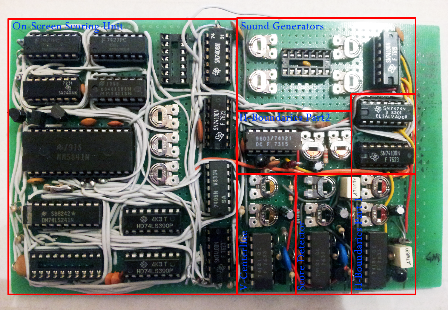
I hope to finish it till next week. I'm so excited about the on-screen scoring! Hoho!
UPDATE 2:
The photo above has been updated. A rainbow of wiring arrived in my mailbox today for connecting the extensionboard to the mainboard. I plan on drilling 5x4=20 holes in a corner of the mainboard for a big header so that I easily can connect/disconnect the extensionboard to/from the mainboard. At the moment, 16 of these pins will be used (a bundle of wires hehe).
UPDATE 3 - 24th of May, 2015:
After a few months of my economy going berserk, I am now back.
The wiring method mentioned above was too stiff and bulky. Instead I glued in a ribbon cable solution which is a much more workable design and easier to move around.
At the moment, this is what comes out of the console:
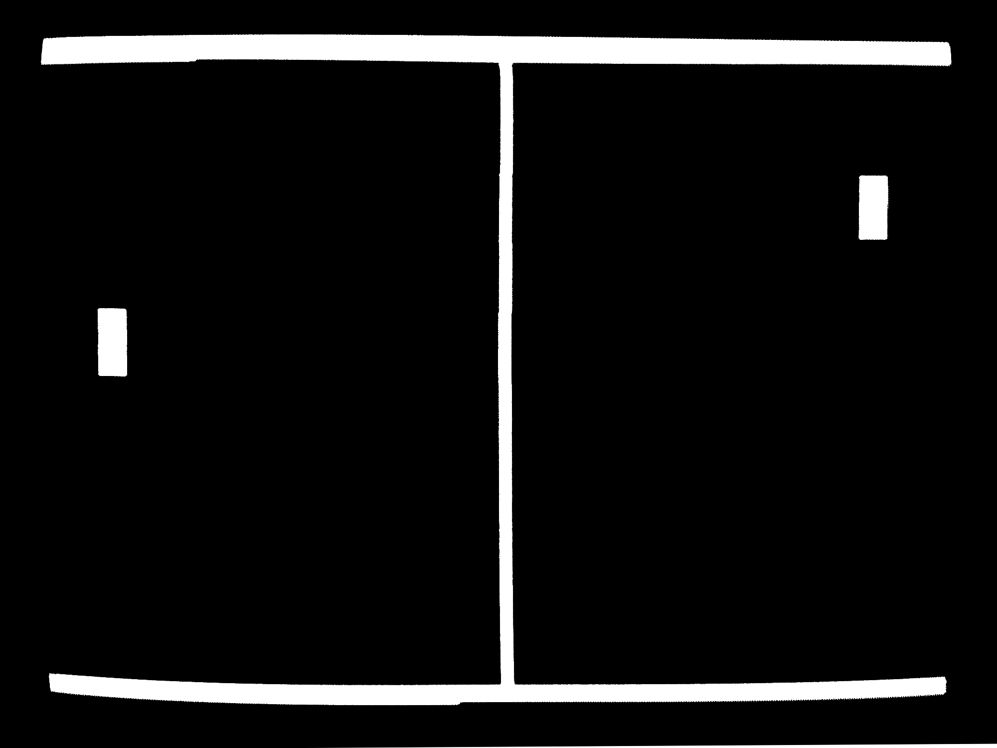

Note that, in the left picture, the ball is broken/invisible.
The extensionboard is nearly completed, the only section remaining to be wired are the sound circuits. The components I ordered from ebay last year were very cheap and therefore bigger than they need to be, I'm afraid that they won't fit in the small area I've reserved for them. I will need to order more, smaller, components for this and pack them very very tightly to make everything fit. But I have tested the sound circuits on a breadboard and I can confirm that they do work very satisfactorily.
The MM5841 isn't working either, there's no video output. I suspect that the syncpulse level-shifters are too basic for proper operation. There are better example circuits for level-shifters in the datasheet which I will look into.
Also, the boundaries have stopped working. Either the boundaries are invisible, and DO work. Or, the boundaries are visible and DON'T work and makes the ball invisible. I'm really confused, but I think it may have to do with the old TTL logic that is present on the extensionboard. Well, hmm.
Oh yes, I have been researching triangle wave generators and I've finally found a perfect replacement for the ball circuits! Using an op-amp, a resistor, and a capacitor, a perfect linear rise and fall voltage that is dependent on the input signal level can now be achieved. I have yet to try it out, but in principal it should more or less be a working solution.
Preliminary schematic for the "fair" ball integrator and controller:
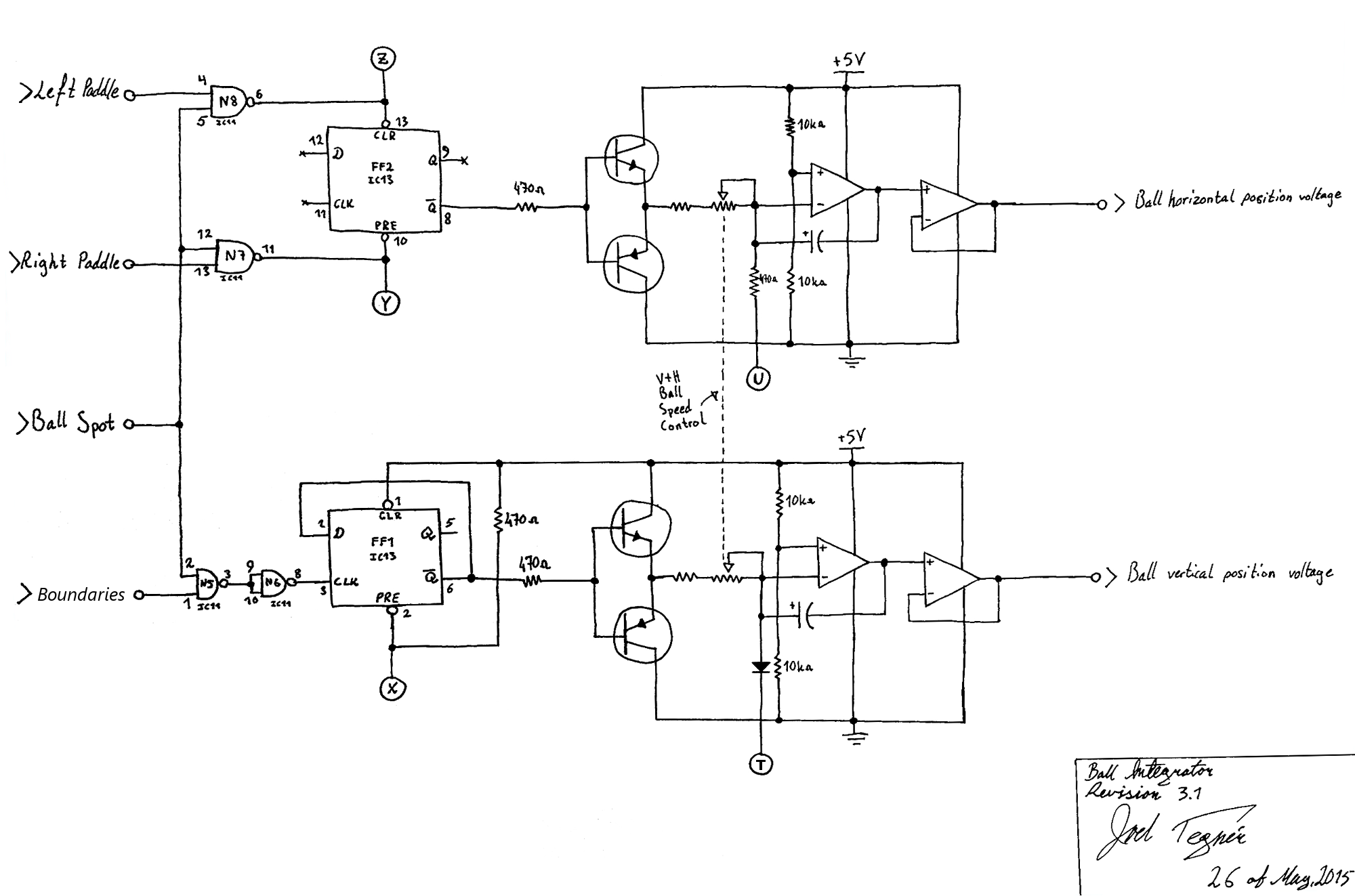
This all initially started out as a build-by-plans project provided by the Elektor magazine issues. But over time, my designs and improvements has taken over and assimilated the original circuits provided by Elektor in such a major way that I can now almost call this my own design. Still, it is far from done. The video stutters, the top/bottom walls are not working correctly, the video summer is not giving the right brightness or video-to-sync relationship, etc etc... Circuits are being revised and will be scanned and published soon.
Next thing to do: Fix the damn boundaries...
UPDATE 4 - 10th of June, 2015:
At last. After days of searching for errors on the mainboard regarding the broken ball, the fault lies in the extensionboard. A wire going from pin 6 on the ball width one-shot being pulled to ground through an unused NAND gate caused the ball horizontal width not being drawn on the screen when the extensionboard was connected. Correcting the connection solved this and the ball now bounces happily all around the screen.
The game is now fully working again, with boundaries and all. The next thing to do would be either to add a dotted centerline (easy, as the extensionboard has an unpopulated IC socket, and some free gates), or to replace the ball integrator circuitry with the one design that I have previously come up with.
UPDATE 5 - 11th of June, 2015:
A modification of the centerline video generation has now yielded a dotted centerline, with variable dot pitch.
