"BCD 7"
Intro
At the age of 13/14 I started getting interested in digital logic circuitry. The following project was the first ever project I designed myself. The one person who inspired me the most to design a TTL clock was Hans Summers.
In the beginning I had a hard time understanding the digital world, especially inverted clock inputs. To be honest I was hopelessly lost, but I was determined to know more. That's when I found Hans website. After reading about his BCD clock I grasped more and more knowledge about the wonderful digital world of electronics.
At first I planned to just build a simple BCD clock. After some more thinking and tinkering I added 7 segment displays and eventually an alarm function to my design so that the clock would view time in both BCD and on 7 segment displays and so I also would be able to set alarms for school.
But just when I had most of the designs done and written down on paper and I had started building the thing, the wave of interest for the project when down to almost nothing and the project stood still for about 4 years.
And now, 4 years later, I got an urge to start working on it again after seeing it laying there all dusty on the shelf. But this time I had other more advanced plans for it.
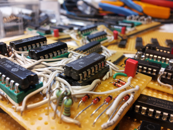
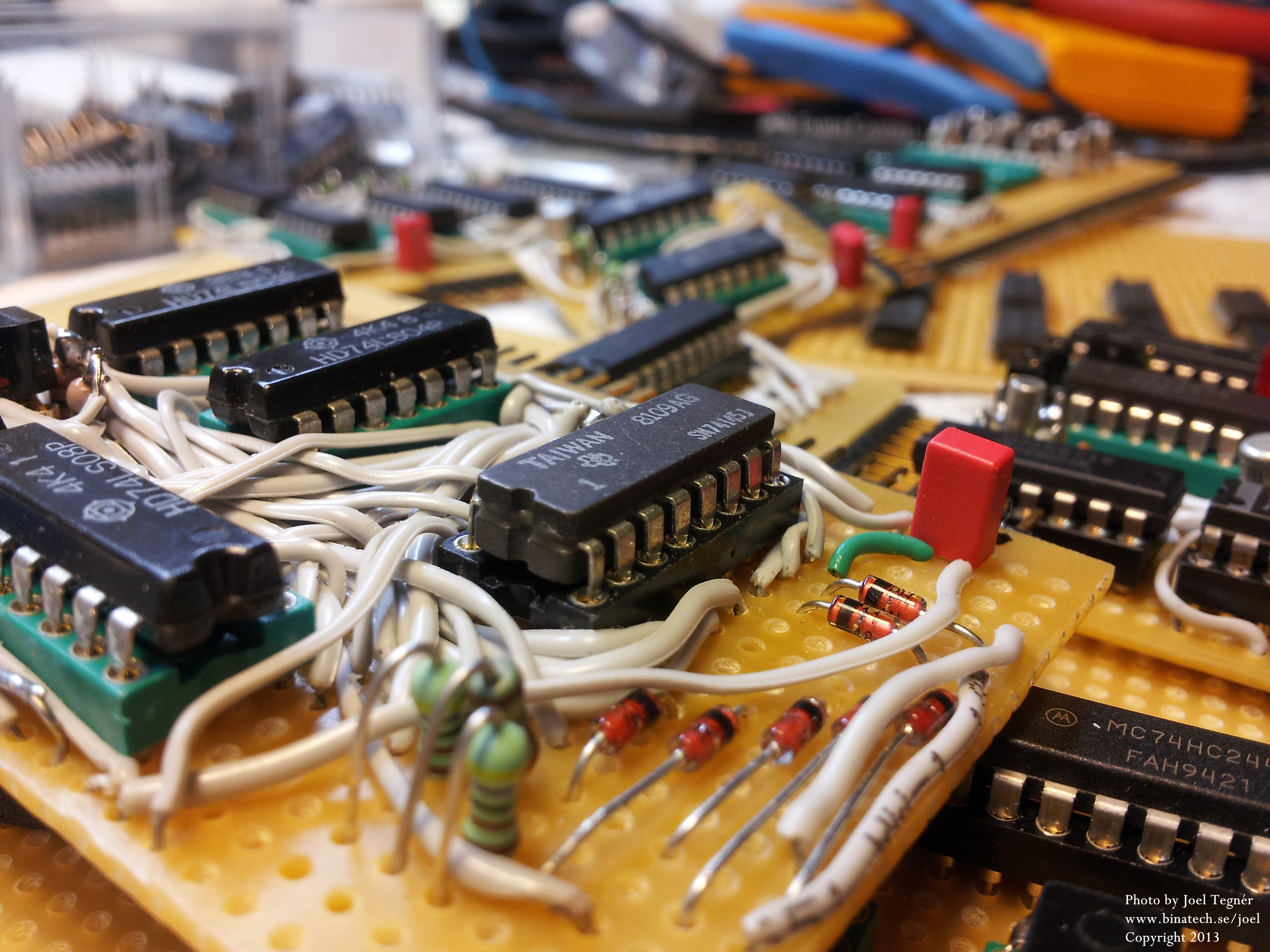
I've now totally redesigned the whole thing to support other fun stuff. But the same basic idea is still there. I decided to have different modules or plug-in cards that would be placed in connectors on a motherboard. Building it this way makes it really easy to add on other modules in the future if I so wish.
It now has the following functions:
Month display represented in three alphanumeric digits (Diodearrays!)
Day display
Year display
Hours display
Minutes display
Seconds display
BCD readout for hours, minutes and seconds
Alarmsetting with brerereeep, brerereeep, brerereeep, brere... signal
Clock from internal oscillator or from mains frequency (50 or 60Hz)
Circuit Explanation
The reason I thoroughly explain everything on every circuit is because I know how very much confused I was when I started playing around in the digital world. =)
The AMDDs
The "Alphanumeric Month Display Decoders" aka AMDDs as I call them, consists of a total of 235diodes arranged in a specific diodearray. They're plug-in boards of which each of them decodes decimals 0 to 12 (coming from the Month Decoder) to 16 outputs driving each of the 16 segments of each of the three alphanumeric displays.
Month Decoder
Decodes the Month Counter binary code into four inverted outputs named 28, 29, 30 and 31 for selecting the right day count for the current month. It also provides inverted decimal outputs using transistors for driving the three diodearrays (AMDDs) and alphanumeric displays.
Clock Divider
...
You know what? I'm abandoning this project. It was an incredible journey and I learned a lot from it (such as multiplexing, powersupply dimensioning, signal levelshifting, diode arrays, ...), but it's too complex for a simple clock and I feel that it is just not worth completing, at least not at the moment. Perhaps in the future.
In time, I will publish all my designs and revisions that I have drawn. It is not completed, design-wise, and some of the designs are very crude, but nevertheless they will be published for the ones interested.