I recently discovered and modified a Marantz CD65II player
and saw that the player is soon become to be an extinct player
because the hardware isn't any longer with us.
Hrmm... someone says, there is a lot of new hardware that is better.
My reply is, offcource, but I have heard a lot of stories
and tales about Philips efforts when it comes to this genuine
16 bit DAC. There is also a wast majority of people liking the
sound of this allmighty queen of all 16 bits DAC.
Everyone seems to have good word for it. I know, It's madness to pay a fortune for a S2 crown version of the TDA1541A but It's about the same happening with the allmighty queen of tubes, the double triode ECC803S. I have myself had the opportunity to buy a sleve cheaply and was amased how much money I got when selling it on E-bay. It's like "Everyone whant's this, it is no longer in production" and finally ... I want it. Then the market prise rises to the hypes border, which could be very high. :-D
-OK, Back to the picture above. This is a kit bought from Ebay and China or Hong Kong (AnalogMetric) They are very forced and professionell and even though I have discoverered some problem with the schematic they are willing to help. Kikitronic is the Ebay shop for that company for the moment. They have copys of very old constructions and some on the DIY Audio forum claims that they steal property. I have not decided what to think in these matters yet.
Updated 9 feb 2010 ... and under progress
This page is written in the
meantime I research and test my findings. Some of the text have
been ripped or edited and altered along these days. I also present
it as a kind of "blog" to this project. Please press
F5 button now and then, so you get the latest updates refreshed
to your browser.
Also,because english is not my native languish I try to change
and do the best I can to keep all the information at this page
understandable.
It'll be my pleasure if some you find my research of value.
More then one year has passed since I bought
this kit and I have still not finished this project. I'm glad
I didn't. Why spoil all the fun there is to learn and do modifications
to this kit.
The kit is good and the sound is very good but I have now had
time to really test things out under some days with lots of testing,
listening and modding. I wanted to do some of the mods described
on different places on the net when it comes to get the most out
of this DAC.
There is another lunatic out there, even more crazy then me, who is modding and testing this kit right now. It's Mr. Fikus or the man who is "tubing" all his DAC's, the lampizator man. He call this DAC the green DAC but this is the same kit allright, even though my PCB is blue.
Anchors on this page, and in following order:
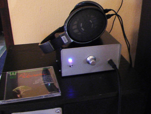
This is my first DIY headphoneamplifier i did 2 years ago. I got very good help and learned alot from the DIY audio forum member Nico Ras. It's a class A amplifier with very high bandwith. The headphones is, hands down, the best there is for the money I would say. They are also very good for OTL tubeamps because they have 300 ohm impedance which make it easier to drive. I use them in my livingroom for my second DIY headamp, with tubes.
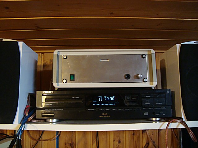
I use this old Philips player as the CD
transporter and use the SPDIF to my DAC's input receiver, which
is the Crystal CS8412. It has one of the better transports and
is also a spare part for my Marantz
CD65II. The CDM4/19. The player has a A-B button which you
can use to repeat snippets. Perfect when you want to do long tests
with the test CD i have made. It's also good for practising the
guittar and want to copy that Eric Clapton lick exactly right.
I bought it for 1.5 $ at an Internet auction. Good deal don't
you think?
The amp on top of the player is another DIY project, the Kleinsmidt 10A.
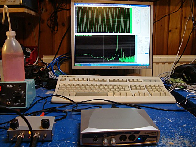
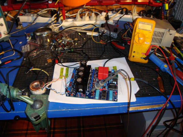
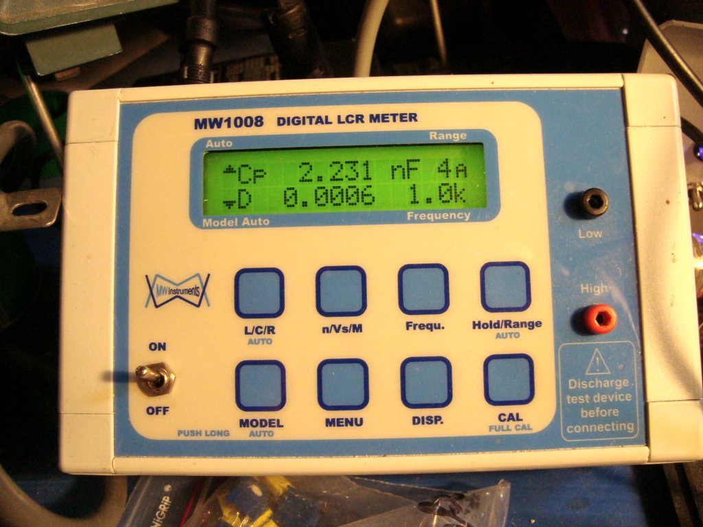
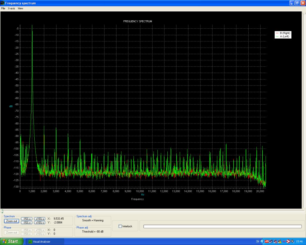
These days we have computers to do nice
FFT measurings. This is what I use. Sometimes I also use the Rmaa
software for amplifier testing. Lately I have also tied it with
my DAC testing. You generate a Testsignal (wav -file) from inside
the Rmaa software. Then you burn that file to a "music"
CD and run the record test.
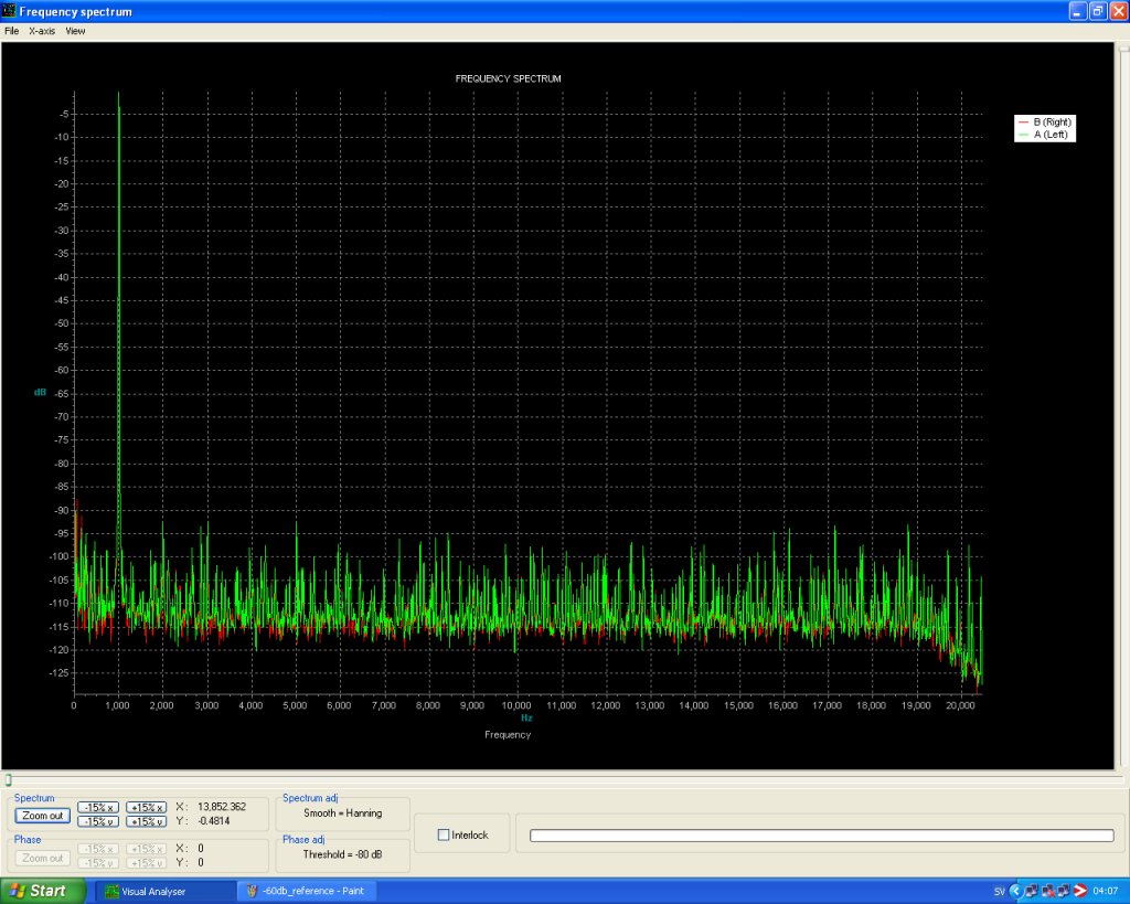
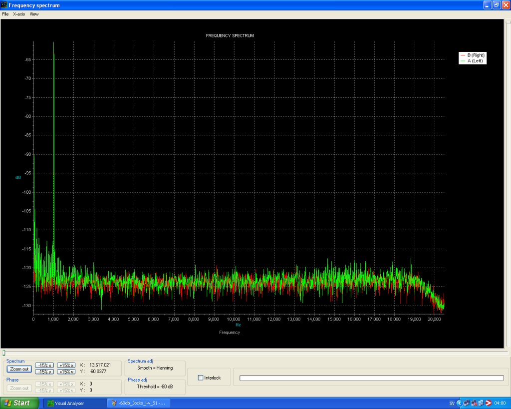
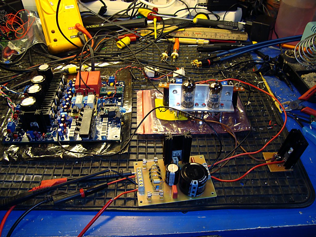
Picture above is DUT for one channel of the tubed I/V amplifier
later down this page. Below is the reference for this setup. The
first graph show worse numbers then it is on the measurings futher
down because I had to use the inbuilt amplifier in my measuring
interface. But the scope-cables and cheap RCA phono and linecables
are the same as in the tests below. The second graph, -60dB is
exactly how it's setup but without the tested DAC. I'm not telling
you this is the best test setup in the world but it gives a good
hint on whats going on and you could also compare the different
approaches for the I/V stages on this page. The two CD signals,
0dB and -60dB, i got from Pedja Rogics site and burned on a plain CD.
The never ending question among DIY people
is if you should run your DAC without oversampling or with it.
And also NOS or NON OS vs. reclocked over sampling. After several
days of listening and shifting back and forth I decided to stay
NOS, in other words without oversampling. The sound was better.
There was a kind of glare or grainy but silky or smeared highs
the NOS didn't have. I think that this is what most people say
about NOS. It's not that much upper highs. The diference is not
large but it's there, maybe more or less depending which DAC kit
you have. There are measurings elsewhere on my site showing the
difference in the upper highs.
As a matter of fact there was win win everywhere going NOS. But
to fully understand that read on. The NOS for me hangs very much
together with the reclocking option you can read about in the
next subject.
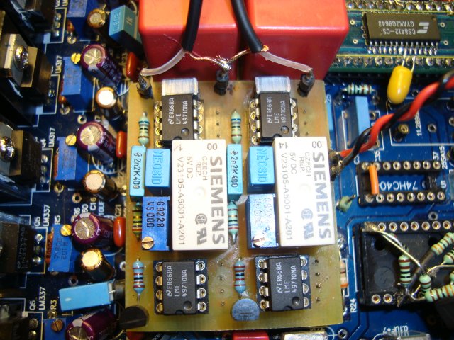
Anyway, the only thing you need to do with this kit to run it NOS is to take out the SAA7220 chip and put in an IC holder which are strapped like the picture below shows. Picture is from a post by Elso Kwak in a thread in the DIY HiFi forum.
I then got some nasty cracklings in the sound if I didn't load the digital lines with something. It was enough to just measure with an oscilloscope probe and the cracklings dissapeared. So I ripped the clock and divider all out. Read on
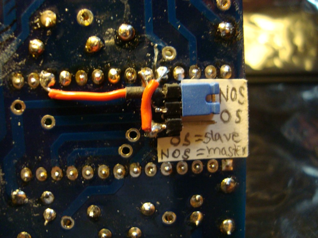
the DAC now is dead silent between tracks. There was a 1.5kHz sinus very low down on the right channel when running OS, you couldn't here it when the music played but it did annoy me. So, I have ripped it all out. The Xtal and the logic for dividing it to the SAA7220. The clock pulses from the onboard clock and logic going to the SAA7220 also looked very ugly on the oscilloscope. More like weak distorded sinus signals then the pefect pulses coming from the CS8412 directly when running master. This is a thing to try if you will listen to NOS but do not want to recklock on this kit, or maybe others as well. Put the CS8412 in master mode. Which means change the pin # M2 to ground instead of 5V. As this kit comes it is jumpered as slave and then the reclocking takes over. The picture below shows how I can switch between those two modes. The label is misleading because this has nothing to do with NOS or OS. I taped that label on before I fully understood the concept. There is also misleading information out there telling you that this has to be done to run this particular DAC in NOS. It isn't, see above. I recomend to run this DAC without reclocking if you want to go NOS.
Anyway, with the ripped out parts and particularly the SAA7220,
I could fit another mod on an IC holder in place there. The I2S
attenuator mod. described next.
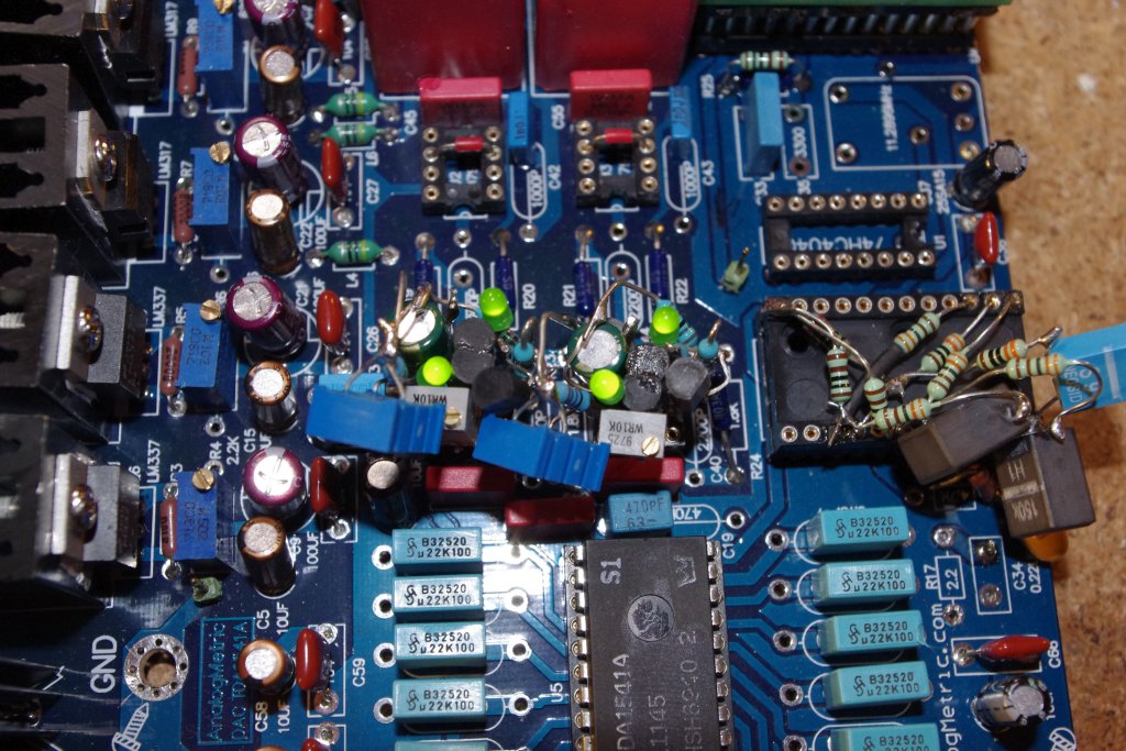
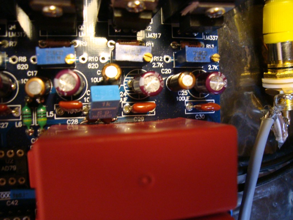
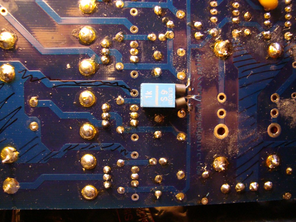
To the right at the picture below is another IC holder with some attenuator stuff for the digital lines. This is one of the win win situations I mention above. When I allready decided to go NOS I can build my attenuation mod on this IC holder instead of cutting the board so that it would be hard to comeback to where it was.
There is several flavour of this mod floating and I have done oone of them which works great.
Schematic is still to come .... stay tuned.
There are a lot of discussion on my favorite forum, the DIY audio forum, about this modification. I will not link, you have to search. Even though there are witnesses telling about a "wow" effect I am a disbeliever in this case. Maybe because I didn't have any success with the easier trials. A big blob with several outside logic circuits didn't catch my interrest to the border where the fun and pleasure of trying really could get me a reasonally good effect of a really useful mod. Also when I read some "white papers" from highly regarded engineers how the TDA1541A, and in this case, how the DEM oscillator works in that circuit, I backed of. I will not do any mod here. I do not believe in syncronized DEM clock. Stochastic it is and stochastic it will be, read on.
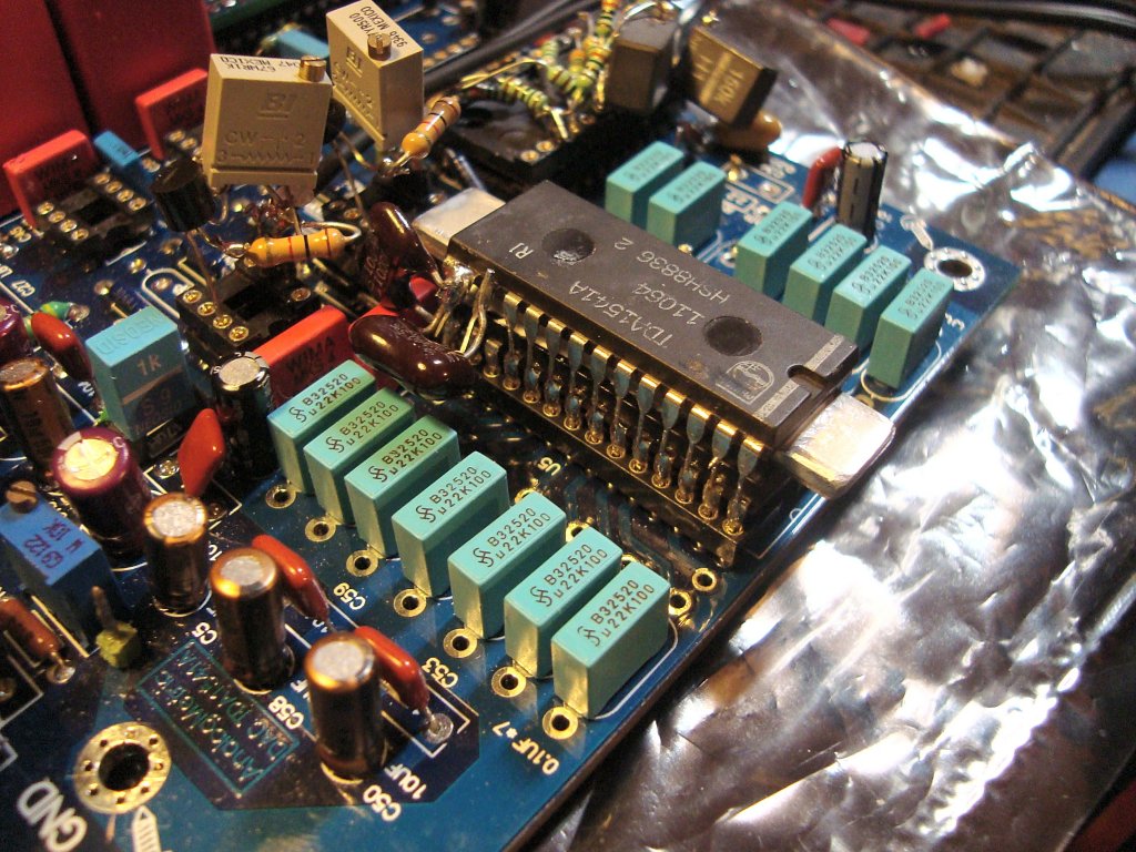
This is something that can give you better sound. Here under is a picture that gives you an Idé on how crazy I am. I have done so many tests and fiddlings so I can say there is no such thing as "this it what you should do" so that everything gets perfect. You are on your own here but pictures below gives you a hint and I will also tell you where you should look more carefully. It's all about using some more or better decoupling capacitors.
Here are some suggestions on decoupling caps around the OP's and the TDA1541A and also the SAA7220 digital filter if you are going OS.
TDA1541A
Around the OP amplifiers
Again I think it's very hard to hear any difference. If someone switched between a S1 crown and a normal on my system, without me knowing, I would have difficulties to hear difference, if at all. I think my S1 sounded more open and airy but when I measure the distortion with FFT the graph says nothing different from the other chips I have, including the R1 version. On the other hand that is the same with the OP's. No difference when measuring THD+n but small individual coloration when switching between them... or am I deluding myself? I really don't know. Maybe I don't have the golden ears everyone else seems to have.
I have now gone to another modification instead of using my S1 crown DAC. Piggybacking another DAC on top of the other
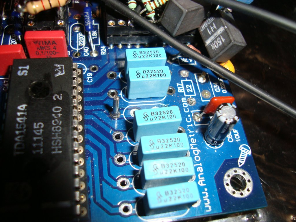
This kit comes with good 10uF WIMa caps.
I have done some listening tests and took them away completely,
bypassed, because I have a cap at the input of my headphone amp
used for the listening sessions. I couldn't here a difference
at all, even if I would like to. So, then it's not any use of
trying another one is it? If someone have one he thinks color
the sound in the right way and propose to try it I don't think
I will. No. I don't like that idée. Giving plenty of money
away to get a colored sound. I'll give it a try another time maybe,
but not on this DAC.
Maybe I will see the light and also become a capacitor fetishist,
some day, but not for the moment.
Inspired by my most visited forum about audio, the DIY Audio, I had to try the piggyback style of this DAC. Some have done it with everyting separate, even the decoupling caps. I have got som hints from erin (again another DIY Audio member) to just solder one TDA1541A on top of the other one and he was .... satisfied (like whooah ;-) ).
I have the most free time att nights so.. one of this nights I went for it (zoombie at work the day after... )
I kept the DEM clocks separate as of erins tip. But I also tested a "syncronisation mod" a'la ecdesign (again another DIY Audio member) For now I have the clocks separated again. So no 100pF between the two DAC's leg 16, see explenation below. Stochastic it is and stochastic it will be, read on.
All in all explained:
Bend the legs 16 and 17 out from the upper IC's body and do not
solder that legs to the TDA beneath. Then solder a 470pF DEM oscillator
cap at this pins. Then, if you would like to try the DEM syncronizing
of the two piggybacked DAC's, solder a 100pF cap between pin 16
of both the dac's. The lower DAC allready has it's own 470pF cap
at the 16 and 17 legs.
I did a 3mm thick and 10mm x 55 mm cooling aluminum "device"
placed in the middle of the two IC's (thermal paste in between).
They get warmer then running alone but not very much. You can
keep a finger on top of the upper TDA as long as you will and
I have learned thats about 45 degrees celcius. When I decide to
finsih this DAc I will also put a small heatzink on top of the
package.
How does it sound? Well, It's subtle but I'm sure it gives even more dynamic, punch and details. FFT measurings also shows a dynamic gain. There is at least 2-3 dB better dynamic measurings from FFT. I will present the final figures when all of this splitted project is done. When my player is more or less finished.
I believe the errors are less when two DAC's co-operate like this. Stochastic it is and stochastic it will be.
It all started with my first post at DIY Audio with this one.

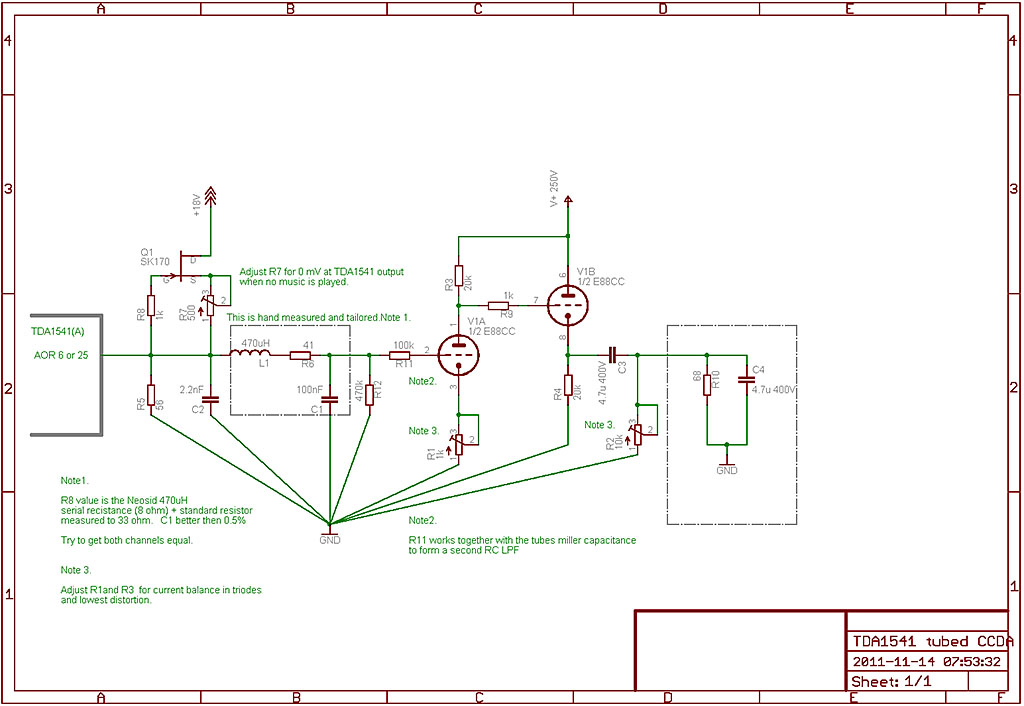
It was a success and I have learned a lot from this work. I have worked it trough and for the moment this is the latest schematic which I am using now and which I probably will use when I "box" this DAC for finalisation.
In the same thread there are some more pictures of the testings and the evolution to the latest schematic above. From the beginning I used a readymade PCB, All-in-one sollution from John Broskie at Tubecad. I got a nice RIAA amplifier with tubes fast and also a test jig for evaluating what this circuit could do as an amplifier after a DAC, such as the TDA1541A.
In short I dicovered that this circuit can
be "calibrated" to give far better THD figures then
one could expect in their wildest dreams! In the notes in the
schematic above you also find the details. It goes like this:
It's of importance that the two triodes work in balance. Equal
current in each one of them. But the real eye opener was to adjust
the load outside the output capacitor to match what you hang on
after this circuit. 10K total load or about 4.1K makes the second
overtone fall from 72dB to 87dB! Yes, I was also chocked. Amasing
results and very rewarding. That is such a thing that makes this
hobby so fun. Everything is not written in stone. You can
also dicover somehing that the rest has forgotten.
Please look for the latest testfigures on the testpage of this DAC.
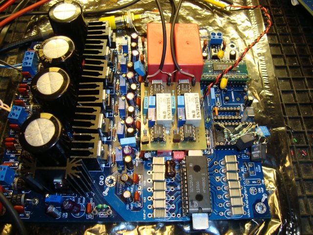
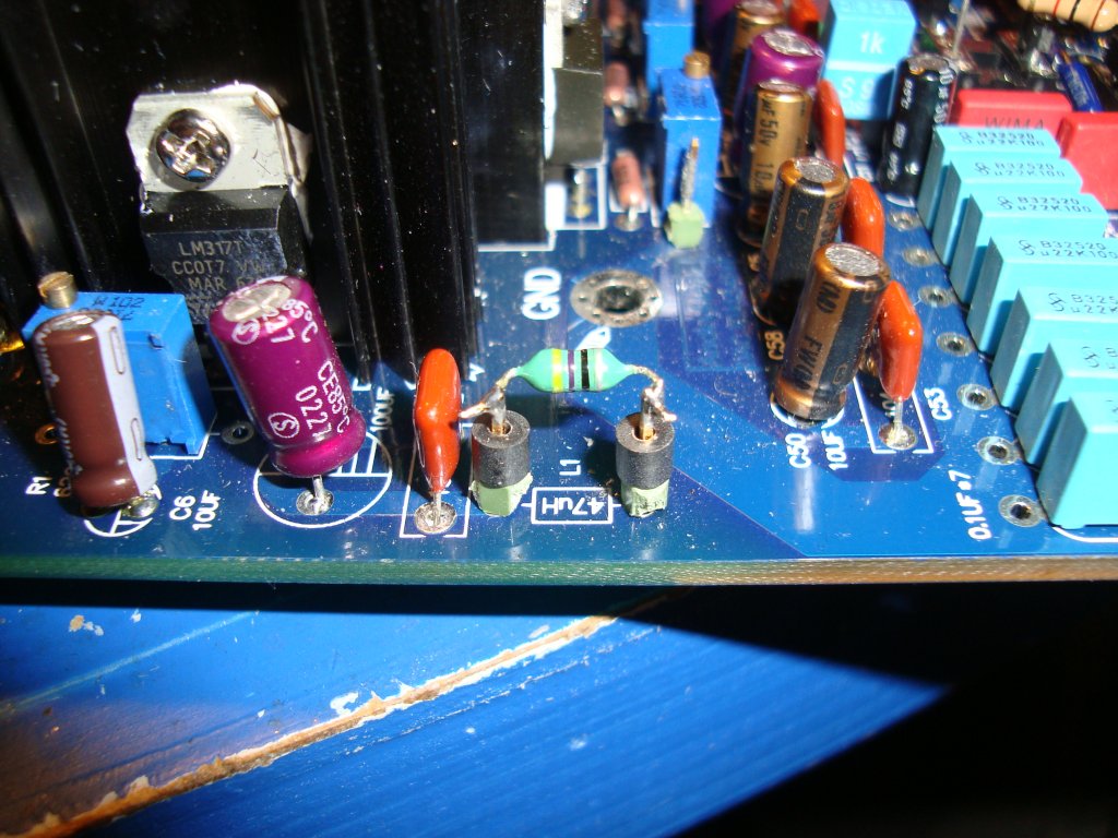
Here under I show you the latest hardware which probably will be the things going in to the DAC box. First picture also shows the HV powersupply and, to the right, the Current source I use for heating the filaments. Same approach on both things as on my XPP headphone amplifier. I will spare my two readymade and tested superregulators for another project. It's overkill and to no use to the better for a CCDA circuit like this. It just wants clean Voltage. And with the stabilized HV Mosfet regulator on the picture ... it will have that. Even more silent then my supershuntregulators.
I have read in some threads of different forums, that the smaller the resistor you have in an I/V stage, the less dynamics there is and "this" and "that" and ... No I will do my own empirical work this time. I give all readers of this page a tip. Please be critical and try for yourself, because you can not trust all subjective thoughts out there. Not even mine ;-)
Most DIY people doesn't have instruments to measure with. You can not use your ears all alone. You will benefit greatly with a soundcard, PC and FFT software to measure THD and also an Oscilloscope to look for such evil things as self oscillation and other evil things in audio.
I have now tested it out, at least when
it comes to THD. There is a limit where the passive I/V
resistor could be of a to high value for a clean sound. Even if
you compensate with the 2mA CCS which I have done on the two graphs
below.
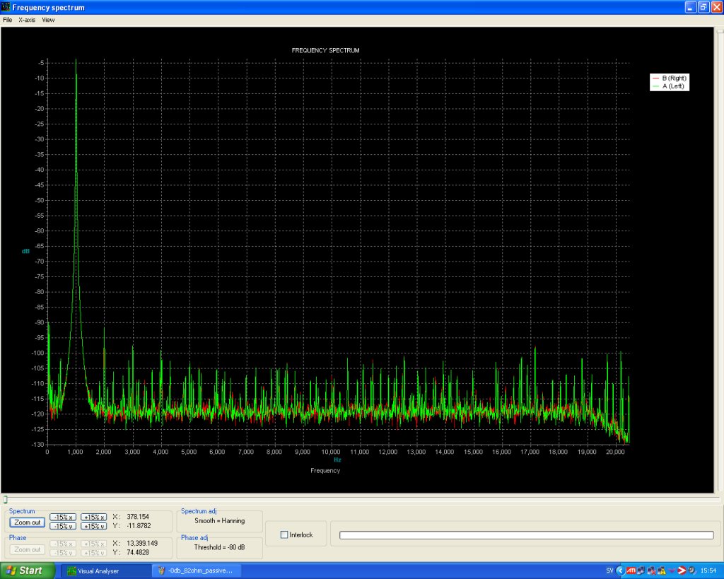
I discovered, trough measurings , that 68 ohm is on the border
to be safe and above, 82 ohm for example, is not safe,
when it comes to analyse FFT graphs (THD figures). This is for
only one TDA1541A. If you have parallelled more you have
to half the resistor value for every pair. So if 56 ohm is good
for one you have to use around 27 for two 15 for four units and
so on ....
Pictures of measurements below is for one TDA1541A chip. First picture -0dB and 82 ohm. Gives about 114mV RMS signal over the resistor Second picture is with 66 ohm which gives about 95mV RMS. This is also a to high value of resistor.
In the schematic for this CCDA tubecircuit
above i have sketched 33 ohm. I would recommend 27 - 30
ohms though. This gives 82-87mV. Then you
are safe but need a high amplification tube. You could use a lower
mu tube such as a 6DJ8 or equivalents but then you will have lower
amplification. On the other hand you will get lower output impedance,
which is a good thing to have.
For the moment I use the E88CC (more or less the equivalent to
6DJ8) and two piggybacked TDA's and a 27 ohm I/V resistor.
It gives me 1.15 V RMS output, superclean sound. The last
tests I did with ECC83 I had 18 ohm metalfilm which gave
me about 54mV and amplified output 2.4V RMS with
a -0dB testsignal, using the second approach of the
sketched circuit above , the one without positive feedback.
I repeat this was also with two DAC's parallelled.
By the way. That metalfilm resistor I use measures 1.8uH inductance which is the exact amount the carbon resistor, Allen Bradley have. So much for the "snake oil" in those resistors. They go for high prices at Ebay.... I also tested a wirewound "speaker filter resistor" which had even higher inductance. So be careful to listen to all subjective thoughts about resistors. I have tried the metaIfilm and the Allen Bradley ones and I couldn't hear any difference. But who am I? A DIY guy without golden ears and without a subjective Hifi audio religion to which I hold on to. Pick your choise but also take care of your hard earned money.
I chimed in at this thread at DIY Audio for mention my findings and also to be a counterweight to the member -ecdesigns-.
.
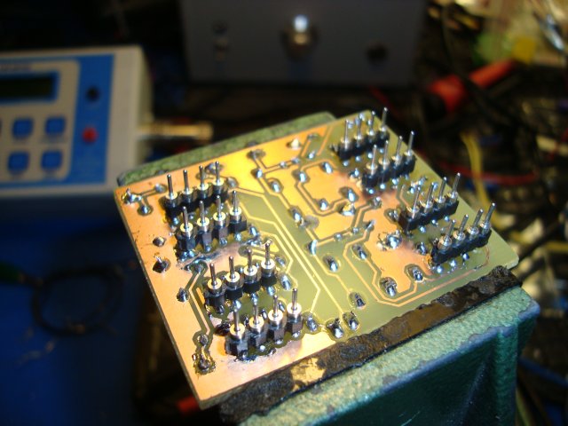
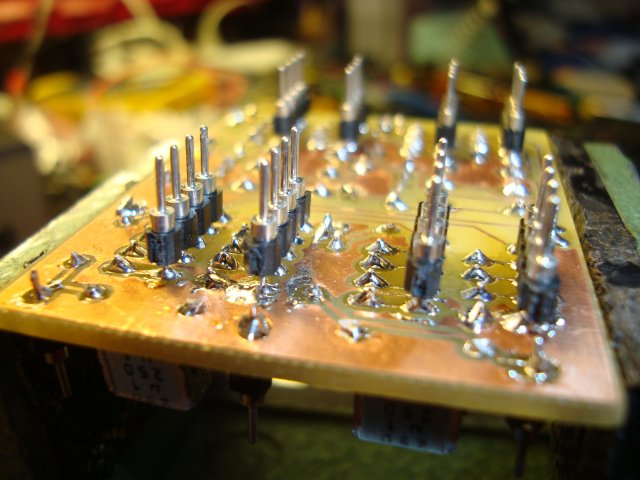
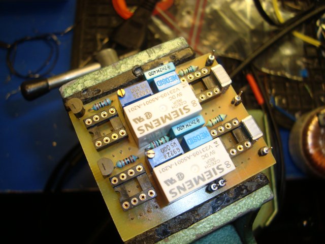
It's very hard to be sure if you do hear progress in sound when modding, testing and listen to your work. So I used Eagle CAD and etched a PCB which I mounted piggyback on top of the four OP IC-holders. On top of that card I have the I/V resistor, CCS circuit and a LP filter for the tubecircuit. There is also two high quality relays so that I can switch between tubed output or SS with the OP's. I have now settled for the lower amplifying device E88CC. So now my DAC gives about 1.15V RMS, both with the LME49710 and the tubes. I have also altered the LPF and feedback on the OP's to match the tube circuit. So when switching there should be very little difference in amplitude or frequency response. Just comparing other signatures which is hard to measure, and even harder to hear ;-). I also have to use a relay at the outputs from the two paths before i send it to the headphoneamp I use for listening tests. Here are some pictures of that work.