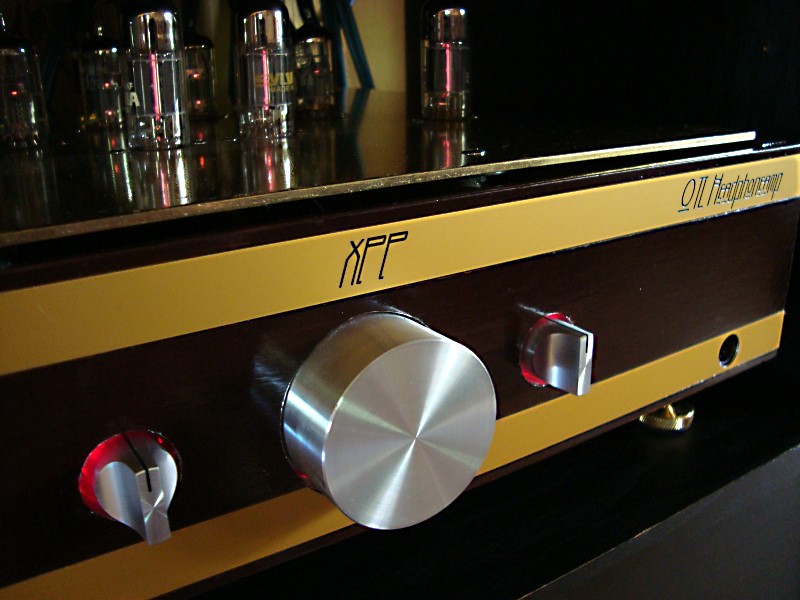
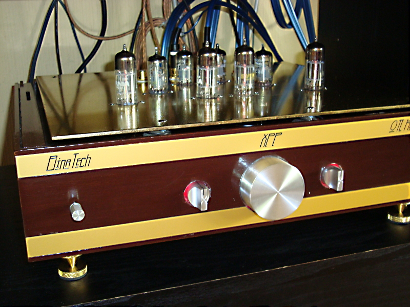
Allthough the fancy picture of my belowed amplifier has my small company name on it, plates bought at nice engraving company i Sweden, it's not any comercial product. It was in a way a trial to get this aftersought amplifier to look a bit more mature and professional then the average DIY audio homework. I also want my wife and the children to think it's OK to populate the livingroom with my homemade stuff without having them embarrased when other guests visit us. Nevertheless, it has potentials to be a seller, I promise. But to build a thing like this by hand and earn some cash ? I don't think it's possible. This is a DIY feast for the eye, ear and mind.
The articles and homepages I have been influenced by is at the references last on this page. These links worked in june -09. I had more references but they are now gone on the net and I didn't write them out on paper before they dissapeared so, .... may those contributors and "Gurus" on the Internet, that still is out there, still serve us well the forthcoming years of the tube amplifiers evolution.
As of may 2009 when this page last was updated
the earlier infant of project and the sketched schematic and tests
before this update, has become a near finished project.
A lot of hard work, learning/reading and a lot of tests and listening
sessions, which I have learned even more from then just reading,
has finally taken me to something I'm going to be pleased with
for a very long time.
The amplifier is now ready and will stay like this version for
a while. Eventually I will do some more tweaking this winter.
Maybe I try a CCS for the negative supply cathode resistor on
the common cathode stage. I will also try to shield the toroids
better. I hope that my documentation of this headphone amplifier,
I here present , can fire up some enthusiasm to some more DIY
audio nerd's out there. I promise that this amplifier will bring
you very high quality listening sessions.
Nevertheless, you are encouraged and welcome to suggest changes
or ideas for this design. If you do try to build it, please tell
me your experiences with this topology. Even your own projects
of similar design is nice to discuss.
I have longed for almost 30 years to build
some descent HiFi Tubed amplifier. The last 10 years I have leaned
towards an output-transformer-less (OTL) headphone amplifier.
Finally I had the skill, parts and workshop to make it happen.
My mind, parts and components have been scattered all over before
the hobby room in the house we bought 7 years ago. But now I have
room for boxes for each project where I collect things needed.
Not bad for a DIY audio nerd.
I finally got hooked on an idéa from John Broskie, published
on his Tubecad
pages, years ago. He called it XXP or figure eight amp. The simulations showed
that it could be loaded with really low impedances and yet have
good distortion figures. I once worked on a test version on the
bench but no listening tests.
Here you can see that early schematic from my hand-sketched prototype
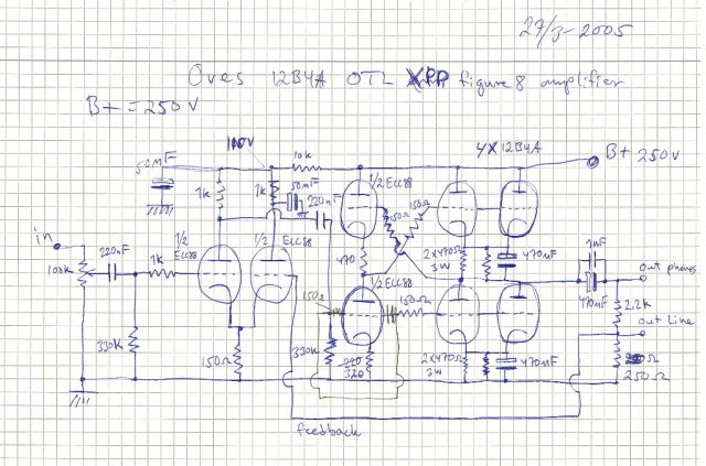 .
.
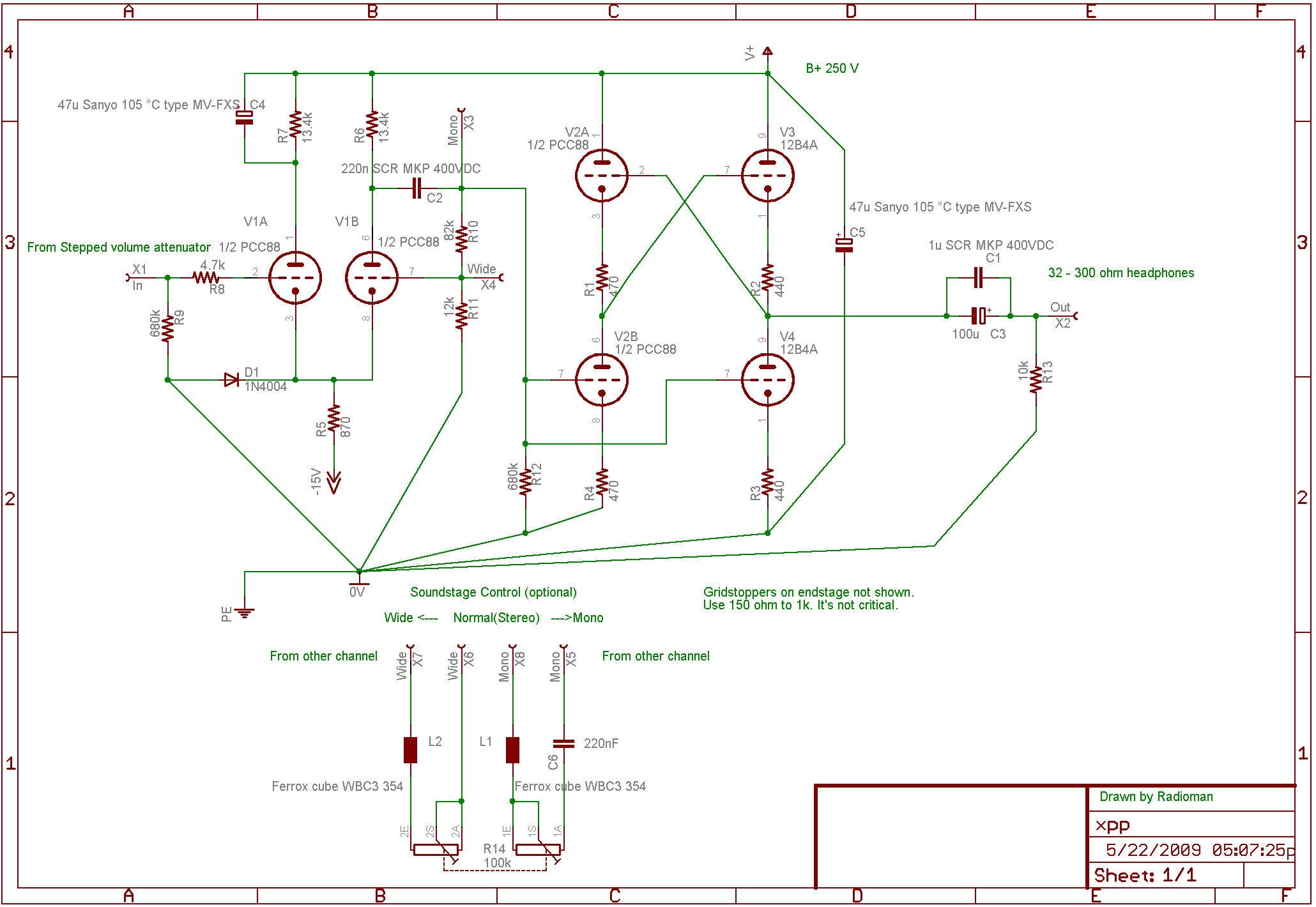
It has matured and is now a bit different and scaled down. Below
is the fully working, scaled down, tested version I enjoy listening
to right now.
I actually e-mailed John Broskie and showed him the first hand-sketched
version above and he answered, but we came to speak about other
things in life. He promised he would comeback to my amplifier
though. And he did in a way, but not as a personal e-mail. I think
that all of the articles about variants on the common cathode
couplings he published at Tubecad, right after our E-mail conversation,
were also for me to read and learn from. In my working amplifier
I now have a fine tuned common cathode stage as front, moderately
local feedback of about 8 dB. Here is a simulation from the Tubecad
software. An old software but it works as good as when it
came out. Works OK in Windows XP and probably also in Vista. I
use a kind of schoolbook schematic but it works o' so beautiful.
I have also been highly influenced by Broskies articles about
this circuits benefits. And more, I now understand why you get
such low distortion figures using it. Please read the references
last on this page.
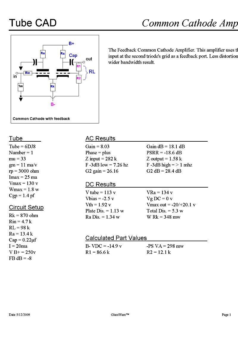
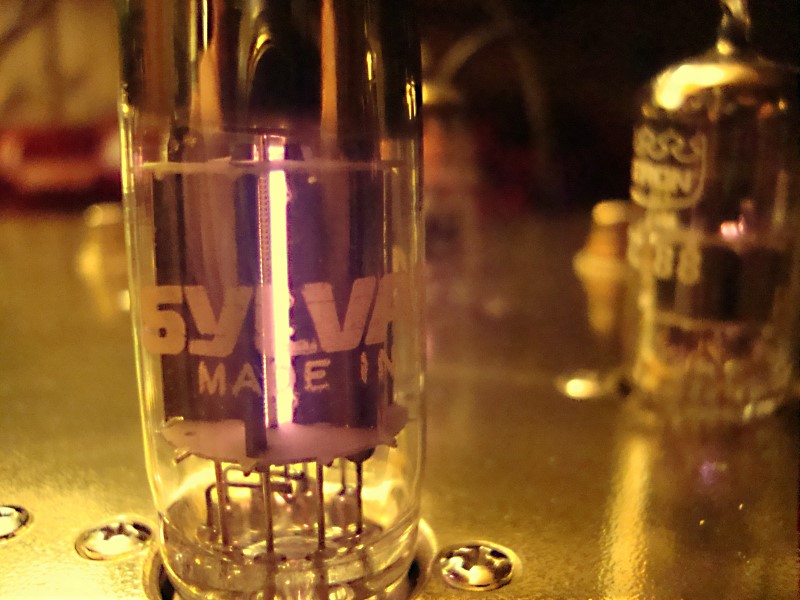
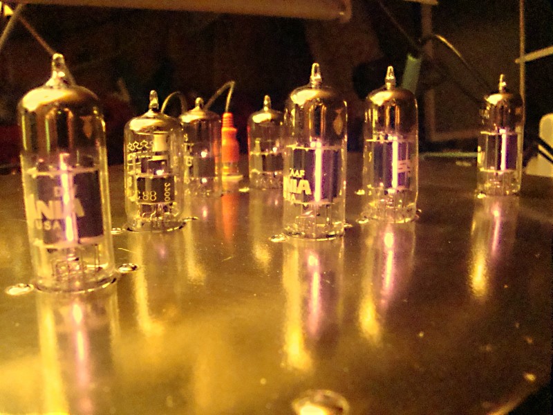
The tube in the simulation above is a 6DJ8 which have the same
specs as ECC88 or PCC88. I chose the PCC88 because it has the
same filament current needed as the 12B4A for the endstage, 0.3A
against 0.36A for a 6DJ8 or ECC88. The PCC88 is also readily available
and cheaper then ECC88 or 6DJ8. Why is it important with the same
current in the filaments? I like to use one CCS for all the filaments
in series. One for each channel fed by the + - 25 V PSU. The tubes
filaments have very low resistance at start-up before they get
warm. Using a CCS to feed them saves the filaments with a slow
startup.
I got the most quiet amplifier when I stargrounded the centertap
of the first transformer. As a bonus I could use the negative
supply to the tail of the Common cathode stage. I start the CCS
filament circuit order with the 12B4A top tube, the bottom tube,
the driver and last the common cathode stage. It's maybe not a
perfect route but there is no danger about max Heater - Cathode
limits.
The testbench version, hand-sketched above, had to many tubes
and capacitors. From the beginning I also had all kind of thoughts
about a monster PSU with transformers as common-mode chokes for low ripple. It all
got out of hands. After that my practical tests made me understand
where I shoot over the goal. There is also to many "no compromise"
projects out there on the forums which set whims in your mind.
More is not allways better, don't you think?
So I have tested and scaled down the finished working amplifier
to what is needed and to what makes sense. This amp can easily
run 300 ohm and down to 32 ohm headphones to ear-splitting levels.
My Right Mark Audio test charts, a link further down this page,
also show that worst scenario, measuring with about 1 V RMS in
to 300 ohm (as I intend to use my Sennheizer HD650 which have
that impedance). A peak level my ears definitely can't stand at
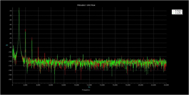
all. I use another
software to show you the FFT's, for both that level and the
lower listening level I use when actively listen for longer evening
session. 300mV RMS (300mV peak with phones). The distortion levels
is then further down and there is practically only the 2'nd harmonic
and a very small amount of the third left to be measured above
the noise floor.
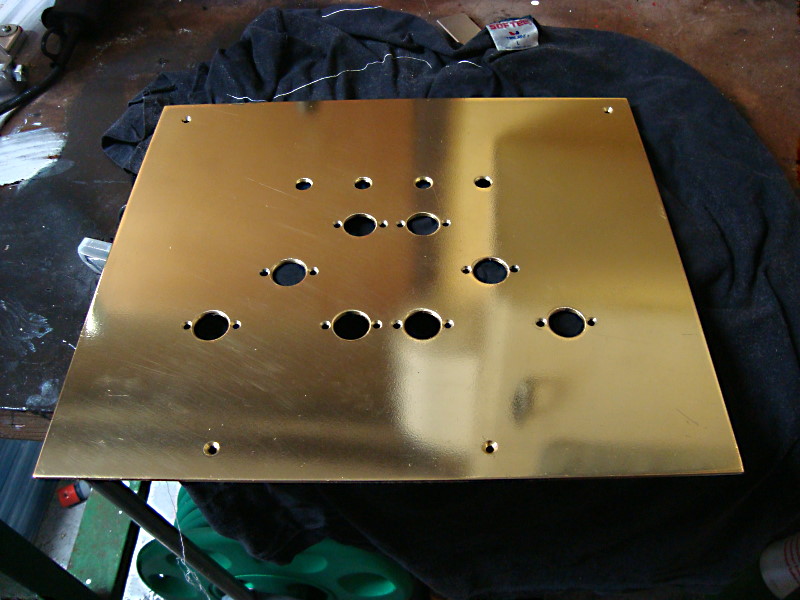
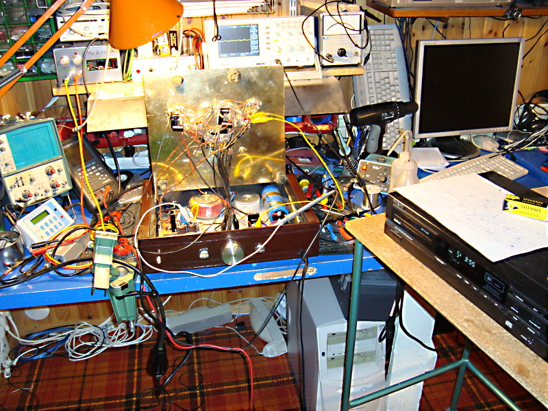
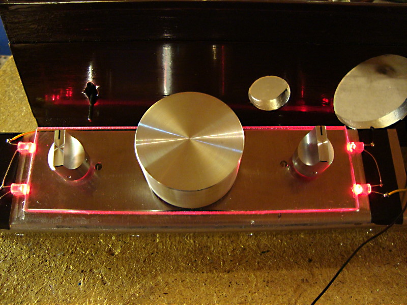
Is the chassis from an old vinyl player? Yes, an old Garrard turntable
have to give the life to this project. The top where the tubes
will sit is solid 2mm brass. Polished and some (mediocre) lacquer
work made it look a little bit professional. This project is going
to have a place in the living room so it better look "better
then the average" projects I have done so far.
On the picture above you can see one of
the old small front plates still left and the factory name "Luxor".
Luxor was once the largest Swedish home electronics factory 40
years ago. They where famous for their TV set's but they did all
kinds of different audio and radio devices. No one will kill me
if I say that they didn't do a very good job when it came to things
with mechanics, like turntables and tape recorders.... Maybe thats
why they used Garrards mechanism to this early -70's model.
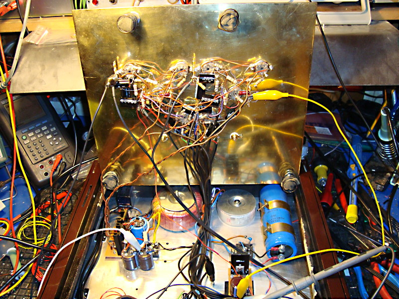
Anyway, where the Garrard turntable mechanics once was is now
my 2 mm. brass plate in it's glory, populated with tubes. Guess
what, it still has spring suspension like the turntable once had.
If there was anxiety for microphony, I'm now confident that it
will not be the case with this tubed baby. Even when I pick on
the tubes with a screwdriver theres not anything to fuss about.
Many people report about problem with microphony but I think this
is mostly a problem for phonostages and when you use speakers.
close to the tubes.
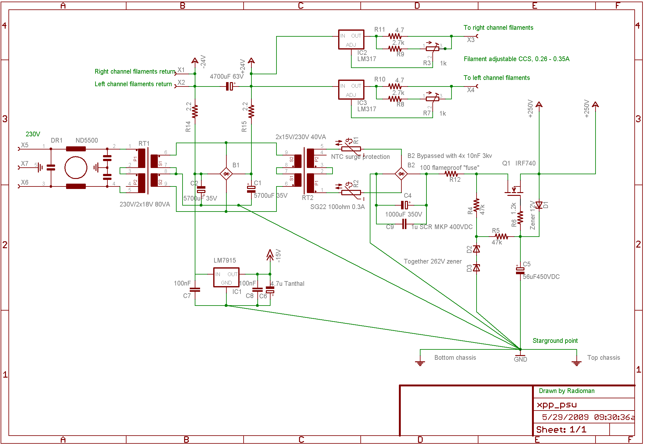
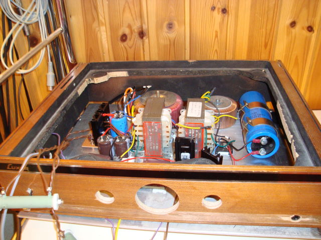
As you can see above there is no amp yet, just the PSU which I
was struggling with from the beginning. I new I had to start backwards
to know what I need to feed the amp that will come. As you may
now, the amp actually is just a modulator of the PSU. So it better
be good from the start. In my case, as I mentioned above, I got
over the top here as well as with the amplifier. The final version
doesn't have those transformers which I tried to use as common-mode chokes. Both for the filament
and HS supply. There is also some reading about using common-mode
chokes instead of active feedforward shunt regulator at Tubecad.
Someone maybe saw the optional soundstage control on the latest schematic above?. Thats the latest experimental tests I've been working on. It has it's advantages to alter the soundstage with mono --- stereo --- or wide (spatial). Think of early Beatles LP f.e. Exaggerated stereo sound one could be indulgent towards listening trough speakers. With headphones it will never give you any soundstage. On the other hand, the "wide" or "spatial" mode maybe pleasent to listen to on certain music material. See my reference links last on this page. A tonecontrol is not this project goal. If I want to alter the tone in such way I use my old OP amplifier equipped Pioneer graphic equalizer. You see, I'm not afraid of "sand" (silicone) .
I was very near to give up this cute soundcontrol.
This control got the amplifier unstable and at first it appeared
as bad contact or bad grounding. All kinds of weared humming depending
on if I hold the cables or moved them. I hooked on the scope and
the hum dissapeared.... I then did a loop on the scope probe,
with the earth connected to the tip. I moved it around the amplifier
and when it started to hum I saw what was happening. There was
not only the audible hum but a 100Mhz oscillation around. I tried
a lot of tricks, including larger gridstoppers and bandage like
capacitors to get rid of it. To make it short the one and only
effective sollution, which was a great experience to learn, even
if I new about them before, was to use ferrite beads. That was,
hands down, very effective! The amp got dead silent when it should
and stable as a rock. Something to consider when you have oscillations
in other circuits of yours.
The measuring tests for stereo separation degrades a little bit
with this control, down to about -45db from the very good -77dB
without it. So if you would like the absolute best measuring
figures you do not want this control. I use this control myself
and love it. On recordings I have listened to I can't hear the
differens when used in the middle (normal stereo). Mixed music
is blended between the channels when the mastermix was done anyway.
Are you a hardcore vinyl fantast? Then look at the stereoseparation
specifications on your cartridge. 45dB is normal for good quality
cartridges.
I have bored a hole on the right hand side of the three case so no one will see the control knob in the front. I like the amplifier clean and sober with just the stepped attenuator (volume control). The one i bought was a kit from John Broskie and Tubecad. Here is the the New-Old TCJ stepped attenuator.
Comments welcomed.
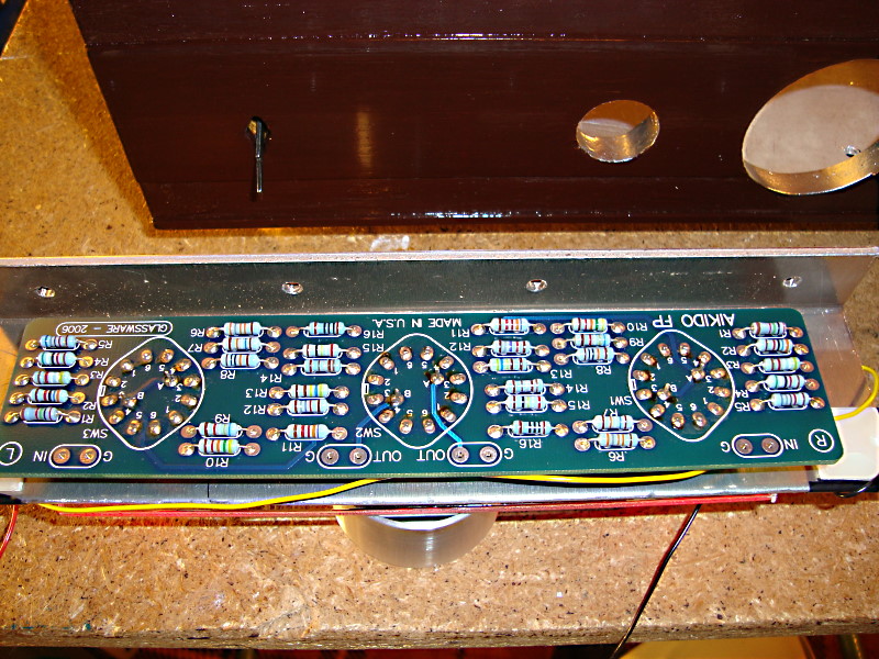
There was no intention from my side to choose any special boutique components. Thats why I use the fairly cheap tubes 12B4A and PCC88. Allthough both of them are beginning to get nice reputation lately. Prizes are probably going up in the future. Still, when it comes to the resistors I have just discovered that the Allen Bradly carbon resistors I use alltrough this design, is of high value for some audiophile's. At least they are expensive on Ebay. I had a lot of them, salvaged from an outranged warehouse, and they are also very easy to read the colourcodes from if you are old and have somewhat muddy eysight. I combine parallel and serial 1 watt's and also 2 watt's so that that they stand at least about double the effect they are going to see in this design. Capacitors are good Industrial quality electrolyth's and good quality metallized polypropylene film type (MKP).
I want to document this amplifiers measuring figures so that one can compare other amplifiers to this one. I have lurked in mostly DIY audio but also other forums of an accepted method of tests and figures that might interrest the average audiophile and technical minded person.
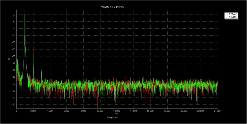
I have finally decided that the Right Mark Audio Analyser is the fastest way to get comparable figures with other DIY people. Use the preset options and go. The tests I present also show FFT's of another great PC software called Visual Analyser 2009 that has comparable figures but also with another voltage level. The one I use for lengthier listening sessions. The 1 to 1.2V RMS which is the tests from the RMAA shown at first here is way to loud for most people. Still the figures comes out nice. Pretty descent for a tube amplifier. Bandwith figures is done outside the PC -DAC word with a function generator and a scope and is about 5hz to near 1Mhz in 300 ohm and under 10hz to near 1Mhz with 32 ohm.
Listening tests says that this amplifier is really very good sounding. I wouldn't dare hoping it would be that good, by far. So I'm proud that it also measures really well. You know I really never ever had the opportunity to listen to a high class tubeamp before. It's very welcomed because it has taken me much time and work to come to this position. I will come back with more detailed reports and comparing it with my former number one reference, the Nico Ras Class A Solid state variant I have used so far. In the meantime look at the tests on the biglink below.
And last the two FFT's from Visual analyser. The first picture with the same amplitudes as when measured with RMAA, 1 Volt rms, and the last one with normal listening levels, 300mV rms (actually only p-p with phones).
The page is in a period of large upgrading. Keep loking in here some week from now. Error corrections welcomed.
References and inspiration:
The amplifier:
Common-cathode amplifier design ideas (TubeCad)
Common-cathode
(a.k.a. cathode-coupled) amplifier (TubeCad)
Cathode-Coupled
Amplifier Developments (TubeCad)
Circuit of the month: June 1999, Common Cathode
Linestage (Glassware)
Gomes
vs XPP (Tubecad)
The missing sonic control (Tubecad)
A Fender-Tone Tube Headphone Amplifier (Alex
Cavalli at Headwize)
Power Supply:
Series MOSFET regulator better with just voltage
ref on gate or with error amp? (DIY Audio discussion)
A
good HV PSU
Mosfet stabilized power supply
Software:
The Right Mark Audio Test Software
Visual
Analyser 2009
Tube
CAD